Material Thickness


How to Select the Right Ultrasonic Thickness Gauge for Plates, Profiles and Pipes Processing Applications
In industrial environments where plates, profiles, and pipes are processed, material thickness is far more than a specification detail—it defines structural integrity, production tolerance, weld quality, corrosion resistance, and regulatory compliance.
Whether you're validating incoming steel plates, monitoring wall thickness in pipes, or verifying material reduction after processing, the accuracy and reliability of your ultrasonic thickness gauge directly influence operational risk and cost control.
Selecting the right solution isn't about choosing the device with the widest specification range. It's about aligning measurement capability with the physical realities of your materials, production flow, inspection environment, and reporting requirements.
The following guide reflects how a technical consultant would approach this decision in a real industrial setting.
Ultrasonic Thickness Measurement in Plates, Profiles, and Pipes Processing
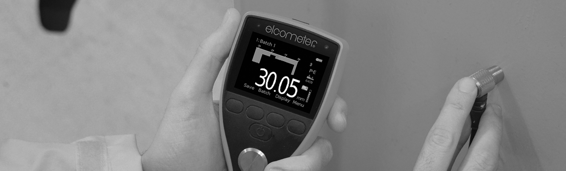
Ultrasonic thickness measurement is a non-destructive testing method based on high-frequency sound waves. A probe (transducer) emits ultrasonic waves into the test material. These sound waves travel through the substrate and reflect from the opposite surface. The ultrasonic thickness gauge calculates thickness based on the sound velocity and the time required for the echo to return.
The key advantage? This method allows engineers to measure wall thickness or material thickness from one accessible side—no need to access both surfaces.
Where This Matters Most
In plates, profiles, and pipes processing, ultrasonic measurement proves particularly valuable when:
- Measuring steel thickness of plates before cutting or forming
- Verifying wall thickness of pipes before welding or installation
- Monitoring corrosion in processed pipe systems
- Inspecting structural profiles in fabrication shops
- Validating thickness reduction after machining
Unlike destructive testing methods, ultrasonic thickness measurement preserves the integrity of the material while providing accurate measurements suitable for quality control and compliance documentation.
Defining the Required Measurement Range for Industrial Materials
Every selection process should begin with the substrate.
Plates, profiles, and pipes processing operations typically involve common materials such as carbon steel, stainless steel, aluminum, and occasionally composites or specialty alloys. The required measurement range may vary significantly:
- Thick structural plates for heavy fabrication
- Medium-range steel plates and profiles
- Thin-wall pipes
- Precision thin materials used in manufacturing
Understanding Range Specifications: A Critical Distinction
A critical practical point for procurement and application planning is that ultrasonic thickness range is not a single universal number—it depends on the instrument family, the measurement mode, and the probe configuration.
In the Elcometer MTG range specifically, the technical specification tables state that the minimum thickness in standard Pulse Echo (PE) mode is 0.63 mm, with an upper range of 500 mm (i.e., 0.63 mm – 500 mm in PE mode). For engineers working with thin materials below 0.63 mm—such as very thin plate, thin-walled sections, or thin plastics—precision gauges (PTG) are required.
The Echo-Echo ThruPaint™ Range Limitation
In parallel, it's important to recognize that Echo-Echo ThruPaint™ (EE) mode is not intended to extend minimum thickness downward. In EE mode, the usable measurement range is more restricted—typically 2.54 mm to 20.00 mm (or up to 25.4 mm depending on material/probe), because the measurement logic is optimized for separating coating echoes from the substrate echoes rather than for very thin substrates.
Matching Gauge to Application
The correct gauge must match:
- The minimum and maximum thickness range
- The material properties, including density and sound velocity
- The expected tolerance levels
- The need for precision and repeatability
Bottom line: If you process both heavy plates and thin-walled pipes, the equipment must accommodate that full operational window without sacrificing measurement accuracy—and that often means separating "general industrial thickness" needs (MTG) from "thin material precision" needs (PTG).
Measuring Through Paint and Protective Coatings in Fabricated Components
In many plates, profiles, and pipes processing environments, materials are coated early in the workflow. Protective coatings, paint systems, or surface treatments may already be applied when inspection occurs.
The challenge? Removing paint thickness layers simply to measure thickness is inefficient and may damage protective coatings.
The Echo-Echo Solution
Modern ultrasonic thickness gauges equipped with coating-ignoring technology, such as Echo-Echo measurement modes, allow operators to measure substrate thickness while ignoring coating layers within defined limits.
For Echo-Echo ThruPaint™ specifically, the coating thickness that can be ignored is up to 2 mm (80 mils). This capability proves particularly valuable in:
- Painted structural profiles
- Coated pipes prior to shipment
- Storage tanks and fabricated assemblies
- Offshore structures
An Important Technical Distinction
It is important to distinguish between coating thickness measurement (which may use magnetic induction, hall effect gauges, or other methods) and ultrasonic thickness measurement of the base material.
In processing environments, the latter is often the critical parameter for structural and compliance verification.
Data Logging and Traceability in Industrial Quality Control
Processing operations in plates, profiles, and pipes industries are increasingly data-driven.
A fundamental distinction: A thickness gauge used occasionally for spot checks differs fundamentally from a solution integrated into structured quality control workflows.
Understanding Storage Capacity Requirements
Modern ultrasonic thickness gauges offer data logging and batch management—but the available storage capacity depends on the model tier, and being precise here helps procurement teams avoid over- or under-specifying.
In the Elcometer MTG range, it is useful to differentiate between mid-tier and advanced inspection workflows:
- The MTG6 stores 1,500 readings
- Higher-tier configurations such as the MTG8 support significantly larger inspection datasets (up to 100,000 readings) along with more advanced visualization functions
When Storage Capacity Becomes Critical
This distinction becomes critical when:
- Verifying steel thickness across large production batches
- Conducting systematic corrosion surveys
- Supporting ISO or regulatory audits
- Providing documented evidence to customers
Structured data collection improves traceability and allows thickness measurement results to be reviewed, analyzed, and exported without manual transcription errors.
The Bottom Line
When thickness measurement becomes part of production validation, digital integration is no longer optional.
Integration with Digital Reporting Systems
Connectivity via USB or Bluetooth® enables ultrasonic thickness gauges to transfer data directly to PC or mobile devices. When integrated with dedicated reporting software, inspection data can be transformed into:
- Professional reports
- Statistical evaluations
- Trend analysis for corrosion monitoring
- Compliance documentation
For procurement and operational managers, this integration improves efficiency and reduces administrative overhead. For engineers, it ensures measurement accuracy and repeatability are supported by defensible documentation.
Environmental Durability in Plates and Pipes Processing Facilities
Processing environments are rarely clean laboratory settings.
Dust from cutting and grinding, temperature variations, moisture, and mechanical impact are common. Ultrasonic thickness gauges used in these industrial settings should be designed with appropriate IP protection ratings (IP54 or IP64) to ensure durability.
The operational risk: Downtime due to equipment failure during inspection campaigns can delay shipment or installation schedules. Selecting robust inspection equipment reduces this risk.
Calibration, Probe Selection, and Measurement Accuracy
Accurate ultrasonic thickness measurement depends not only on the gauge itself, but also on proper calibration and probe configuration.
Material-Specific Calibration
Each material has a specific sound velocity. Before measuring steel thickness, aluminum plates, or composite materials, the gauge must be calibrated against a reference sample with known thickness. Calibration blocks should ideally match the test material in composition and thickness range.
Probe Selection Variables
Probe (transducer) selection influences:
- Measurement range
- Resolution
- Sensitivity to surface condition
- Ability to measure thin materials
Modern ultrasonic thickness gauges may support multiple measurement modes, including:
- Pulsed-Echo
- Velocity Mode
- Plastic Mode (PLAS) for plastics
- Interface Echo (I-E) for layered structures
Maintaining consistent calibration practices ensures measurement accuracy typically within ±1%, supporting reliable quality control and compliance validation.
Real-Time Pass/Fail Evaluation in Production Lines
In processing environments, decisions must often be made immediately.
User-definable pass/fail limits allow operators to detect deviations in wall thickness during measuring. Audible and visual alarms support rapid identification of out-of-tolerance materials before they proceed to the next production stage.
When Immediate Feedback Matters Most
This capability proves particularly valuable when:
- Verifying pipe wall thickness before welding
- Checking steel plate thickness before forming
- Detecting material loss due to corrosion in processed assemblies
Immediate feedback improves production speed while maintaining quality standards.
Application-Specific Selection Strategy for Plates, Profiles, and Pipes Processing
When selecting an ultrasonic thickness gauge for processing operations, decision-makers should align the instrument with the intended application:
- Broad thickness range and coating-ignoring capability for corrosion monitoring in pipes and fabricated structures
- Precision measurement capability for thin plates or thin materials
- Advanced data logging for structured quality control
- Rugged design for harsh industrial settings
The Selection Principle
The right equipment is not necessarily the most advanced model—it is the one that matches your operational requirements without introducing unnecessary complexity.
Material Thickness Solutions Available via Minex
Minex acts as a distributor of industrial inspection and measurement equipment. Within the material thickness category relevant to plates, profiles and pipes processing, Minex supplies the following ultrasonic thickness solutions.
Ultrasonic Material Thickness Gauges Portfolio
| Product | Measurement Range | Core Capabilities | Typical Applications in Plates, Profiles and Pipes Processing |
| Elcometer MTG2 Ultrasonic Material Thickness Gauge | 0.63 mm – 500 mm (PE mode) | Pulsed-Echo measurement, factory calibration, rugged industrial design | General steel thickness verification in plates and profiles, routine wall thickness checks in pipes |
| Elcometer MTG4 Ultrasonic Material Thickness Gauge | 0.63 mm – 500 mm (PE mode) / 2.54 mm – 20.00 mm (EE mode) (up to 25.4 mm depending on material/probe) | Echo-Echo ThruPaint™ coating-ignoring measurement, Velocity Mode, IP-rated protection | Coated pipes, painted structural profiles, corrosion monitoring in fabricated assemblies |
| Elcometer MTG6 Ultrasonic Material Thickness Gauge | 0.63 mm – 500 mm (PE mode) / 2.54 mm – 20.00 mm (EE mode) (up to 25.4 mm depending on material/probe) | Data logging (1,500 readings), multi-point calibration, coating-ignoring capability | Structured quality control in processing facilities, asset integrity programs |
| Elcometer MTG8 Ultrasonic Material Thickness Gauge | 0.63 mm – 500 mm (PE mode) / 2.54 mm – 20.00 mm (EE mode) (up to 25.4 mm depending on material/probe) | Live B-Scan display, memory up to 100,000 readings, IP54/IP64 durability | Detailed corrosion assessment in storage tanks, pipes and offshore structures |
| Elcometer PTG6 Precision Ultrasonic Thickness Gauge | 0.15 mm – 25.40 mm | Plastic Mode (PLAS), Interface Echo (I-E), high precision measurement | Thin plates, thin-walled pipes, plastics and precision manufacturing components |
| Elcometer PTG8 Precision Ultrasonic Thickness Gauge | 0.15 mm – 25.40 mm | Bluetooth® & USB connectivity, ElcoMaster® integration, 40 pass/fail limits | Advanced production quality control, compliance-driven inspection environments[MV1] |
Technical Consultation for Your Processing Environment
Selecting an ultrasonic thickness gauge for plates, profiles, and pipes processing is an engineering decision that affects structural integrity, production efficiency, and compliance assurance.
When to Seek Application-Specific Guidance
If your application involves:
- Steel thickness verification in large plates
- Wall thickness measurement in pipes
- Corrosion monitoring in processed assemblies
- Thin material precision measurement
- Integration of thickness data into digital quality systems
How Minex Can Support Your Selection Process
The Minex technical team can provide:
- Application-specific guidance
- Probe selection support
- Calibration recommendations
- Workflow integration advice
Contact Minex to discuss your operational requirements and receive tailored technical consultancy aligned with your processing environment.
Frequently Asked Questions
Ultrasonic thickness measurement is a non-destructive testing (NDT) method that uses high-frequency sound waves to determine the thickness of a material from one accessible side.
How It Works
A probe (transducer) emits a sound pulse into the material. The sound wave travels through the substrate, reflects off the opposite surface, and returns to the probe. The instrument calculates thickness based on the time-of-flight of that signal and the known sound velocity of the material.
Common Industrial Applications
This technique is widely used in:
- Corrosion monitoring of pipelines and storage tanks
- Structural steel inspection
- Pressure vessels and boilers
- Marine and offshore structures
- Manufacturing quality control
- Asset integrity programs
Its key advantage? It allows thickness verification without cutting, drilling, or damaging the component.
Most industrial ultrasonic thickness gauges are capable of measuring a wide variety of sound-conductive materials, including:
- Carbon steel and stainless steel
- Non-ferrous metals
- Plastics
- Composites
- Certain ceramics
Understanding Measurement Range
Measurement range depends on the specific instrument, measurement mode, and probe configuration.
In practice, engineers should plan around the range of the instrument family they intend to deploy. For example, the Elcometer MTG models measure from 0.63 mm to 500 mm in Pulse Echo (PE) mode, while precision applications below 0.63 mm—down to 0.15 mm—require PTG precision gauges (particularly when using Plastic Mode (PLAS) with appropriate probe setups).
Success Factors
Successful measurement depends on:
- Correct sound velocity settings
- Appropriate probe selection
- Proper calibration
The instrument must match both the material type and the thickness window of your application.
Coatings introduce an additional acoustic layer between the probe and the substrate. In standard measurement mode, the gauge may detect the coating thickness together with the base material, or may require coating removal to obtain accurate substrate readings.
The Coating-Ignoring Solution
However, many modern industrial ultrasonic gauges support technologies that allow measurement of the base material while ignoring the coating layer, within defined thickness limits.
For example, Echo-Echo ThruPaint™ measurement can:
- Ignore paint or protective coatings
- Measure substrate thickness directly
- Eliminate the need for destructive coating removal
Technical Specifications
In practical terms, Echo-Echo ThruPaint™ ignores coatings up to 2 mm (80 mils). Engineers should compare this threshold to their real coating system build (including primers and topcoats) to confirm suitability.
Evaluation Checklist
When evaluating an instrument, verify:
- Maximum coating thickness that can be ignored
- Whether coating removal is required
- The specific measurement mode used
Measurement accuracy in ultrasonic thickness testing depends on several controllable variables:
1. Sound Velocity Calibration
Each material has a specific acoustic velocity. Incorrect velocity settings will directly affect thickness readings. Calibration should always be performed on reference material that matches or closely resembles the test piece.
2. Surface Condition and Coupling
Proper acoustic coupling between probe and surface is essential. Contaminants, roughness, scale, or inadequate couplant can reduce signal quality.
3. Probe Selection
Different materials and thickness ranges require different probe frequencies and configurations. Thin materials often require higher frequency probes or delay line setups.
4. Measurement Consistency
Standardized procedures, repeatable contact pressure, and consistent calibration practices improve repeatability over time.
Quality assurance: High-quality instruments also support multi-point calibration and factory calibration settings to maintain accuracy levels up to ±1% under controlled conditions.
Selecting the appropriate gauge requires a structured technical assessment.
Key Decision Parameters
The key decision parameters include:
- Material type and acoustic properties
- Minimum and maximum thickness range
- Presence of coatings or multilayer systems
- Environmental exposure (dust, moisture, solvents)
- Data logging and reporting requirements
- Inspection objective (routine QA, corrosion monitoring, regulatory compliance)
Application-Specific Examples
For example:
- Heavy industrial corrosion monitoring typically requires broad-range measurement capability with coating-ignoring functionality
- Precision manufacturing of thin metals or plastics requires specialized thin-material capability
- Compliance-driven inspections may require advanced data logging and software integration
The guiding principle: Instrument selection should reflect operational reality, not only specification sheets.
Regular calibration and verification are standard industry practice in NDT and quality assurance environments.
Calibration Frequency Factors
Calibration frequency depends on:
- Internal QA policies
- Regulatory requirements
- Inspection criticality
- Frequency of use
Standard Calibration Practice
Typically, gauges are:
- Verified before each inspection session
- Calibrated using certified reference blocks
- Checked against known thickness samples
Reference Block Requirements
Reference blocks should ideally:
- Be made of the same or similar material
- Cover the thickness range of interest
- Be traceable to recognized standards
Documentation requirement: Maintaining documented calibration records is essential in regulated industries and asset integrity programs.
Thickness measurement is not an isolated activity—it is a core component of long-term asset integrity management.
Data Collection Process
Recorded thickness readings are typically:
- Logged in structured batches
- Repeated at defined intervals
- Compared against historical data
Engineering Analysis
From this data, engineers can:
- Calculate corrosion rates
- Estimate remaining wall thickness
- Forecast remaining service life
- Prioritize maintenance or replacement
- Demonstrate compliance with inspection standards
The integration advantage: In structured asset integrity programs, digital data logging and reporting integration significantly enhance trend analysis and regulatory traceability.